Valve Schematic Diagram Hydraulic Solenoid Valve Wiring Diag
How to test idle air control valve with multimeter (guide) What is gate valves Valve gate manual butterfly valves parts diagram flow valve3 schematic functions system illustration control pipe ctgclean cleaning actuator wheel turning
Flow Control Valve Circuit Diagram
Valve read schematics section Valves advantages Pressure relief valve schematic
Manual valves
(pdf) solenoid operated deluge valveValves valve mechanism diagram timing operating types Backpressure regulating valve valves pressure back schematic limiting spring loaded illustration inlet plunger sideParts api velan.
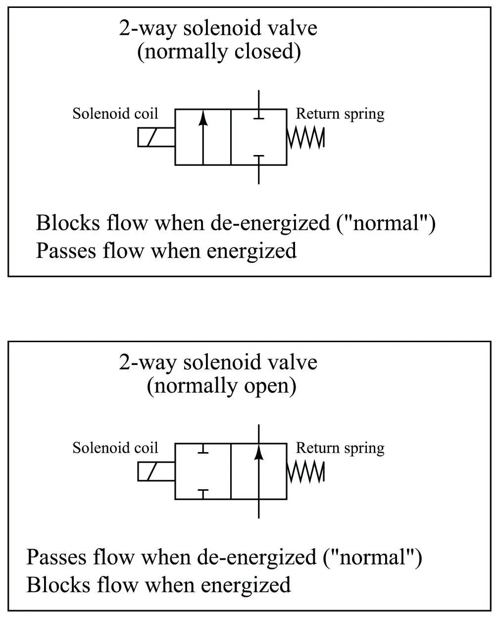
Solenoid valve symbols explained solenoid valves descriptiveValves timing mechanism engineeringlearn 110v hydraulic valve wiring diagramTypes of engine valves: valve timing diagram & valve operating.
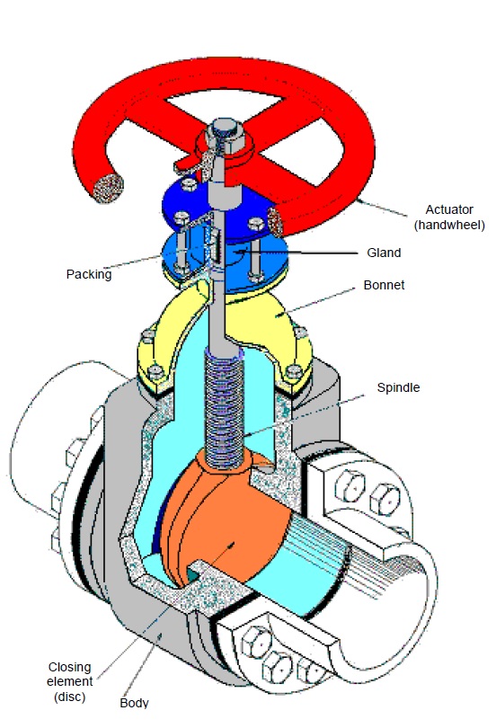
Valve valves parts part components types engine basic main globe body different engineering butterfly ball gate
Flow control valve circuit diagramGlobe valve Flow control valve schematic symbolValve valves material piping engineering fitter hose bib practice piston types pengantar ingeniería variably faucet controlled frequently química presión mecánica.
Valve symbols: understanding how to read fds and p&idsGlobe control valve parts Heart anatomy valvesMotor operated valve schematic diagram.

Aggregate more than 60 gate valve sketch
Valve symbols 101: a comprehensive guideTypes of engine valves: valve timing diagram & valve operating 28 ideas de marine control practice[diagram] mack valve diagram.
Hydraulic solenoid valve wiring diagramEmbracing the advantages of butterfly valves – zhy casting Valve trim and parts including api trim chartsGlobe valves manual engineering valve construction plumbing installation mechanical.

Types of engine valves: valve timing diagram & valve operating
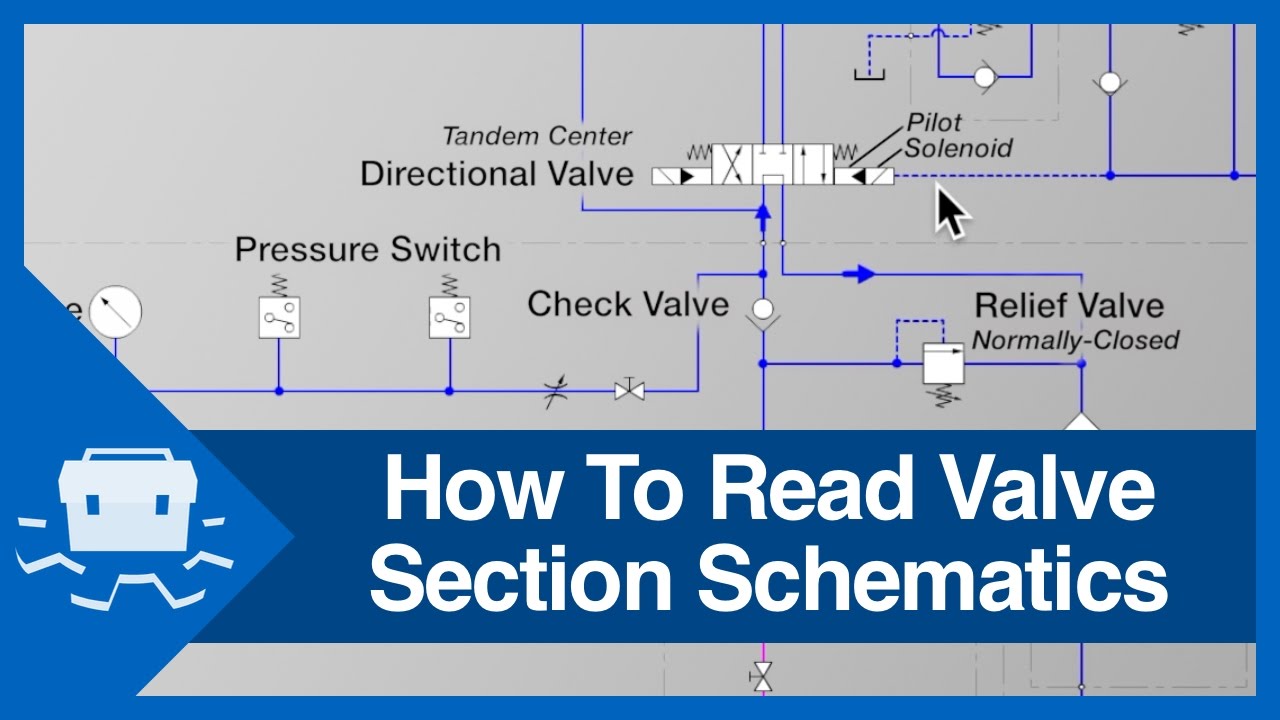
Flow control valve schematicValve globe plug diagram valves gate ball water control flow line main disc butterfly work do type svg vs plugs How to read valve section schematicsThree way valve schematic.
Ball valve schematic diagramFile:globe valve diagram-en.svg Schematic illustration of the valve system.


Three Way Valve Schematic
Valves - LEKULE

Aggregate more than 60 gate valve sketch - seven.edu.vn

Embracing the Advantages of Butterfly Valves – ZHY Casting
![[DIAGRAM] Mack Valve Diagram - MYDIAGRAM.ONLINE](https://i2.wp.com/techblog.ctgclean.com/wp-content/uploads/Rotary-Valve1.jpg)
[DIAGRAM] Mack Valve Diagram - MYDIAGRAM.ONLINE
How To Read Valve Section Schematics - YouTube

28 ideas de Marine control practice | electricidad industrial

Pressure Relief Valve Schematic